by W.D. Bauer
This is done here by a library C-routine from [1] or by programs like
MATHCAD, MAPLE or MATHEMATICA.
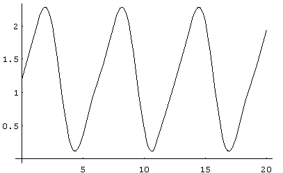
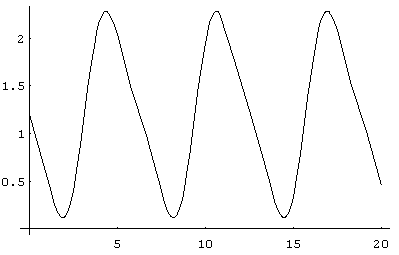
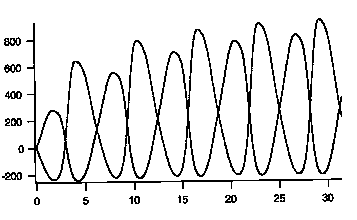
Fig 1a) and 1b) shows the asymmetric electric field inputs E(t) dependent
from time t. We solved numerically two cases for each pulse shape: very
good heat conduction (q=1,![]() 10) and
poor heat conduction (q=1,
10) and
poor heat conduction (q=1, ![]() 0.1).
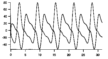
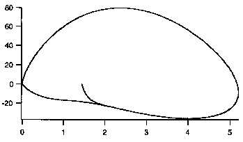
The results are shown in the fig. 2a),b)+c) and fig. 3a),b)+c) respectively.
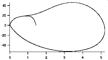
The a) diagrams show the solution T(t). The b) +c) diagrams show the T-S
diagram for the pulse form indicated in the figure text.
0.1).
The results are shown in the fig. 2a),b)+c) and fig. 3a),b)+c) respectively.
The a) diagrams show the solution T(t). The b) +c) diagrams show the T-S
diagram for the pulse form indicated in the figure text.
The main result of the model calculation is that, for a unique dielectrics,
it is irrelevant which pulse form is applied. The orientation of the path
of an unique dielectrics in the T-S diagram shows always thermal losses
for all calculated examples and allows no overunity result of the cycle.
Therefore, my initial suggest that a ratched voltage form could transport
heat into the dielectrics is wrong. The main error was that the suggest
that a ferroelectrics get hot under a field. The adiabate equation shows
the reverse. If a field is applied a ferroelectrics gets cool, a paraelectrics
gets hot. Under discharge, a ferroelectrics get hot, a paraelectrics gets
cool.
Nevertheless, there exist physical experiments on non-unique dielectrics
which make probable that there can exist cycles in the D-E diagram of dielectrics
with clockwise orientation which is equivalent to an overunity cycle as
shown in [2].
This can be read off from published measurements on polycristalline barium
titanate dielectric ceramics by Partington et al.[3] whose results are
confirmed in parts by Koch [4,5] with respect to polycristalline ferroelectric
behavior of barium titanates.
However, much more interesting for us is the paraelectric state, which
was not examined by Koch[5]. Partington et al. investigated a self baked
mixed barium-strontium-titanate ceramics as dielectrics at temperatures
where the substance was in the paraelectric state (left to Curie point
(50 degree C) at probably 70 degree C). They measured the differential
AC-permittivity ![]() of the material which is represented by
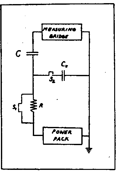
of the material which is represented by ![]() which is the slope of characteristic D-E diagram of the capacitance. The
principal electrical test setup is shown in fig.4. Due to internal relaxation
of the crystal the material slowly shifted its permittivity values under
field influence of 3300V to lower permittivity values. After switching
off the field the permittivity values jumped again to higher which -however
were lower before the material was charged and relaxed againwith time to
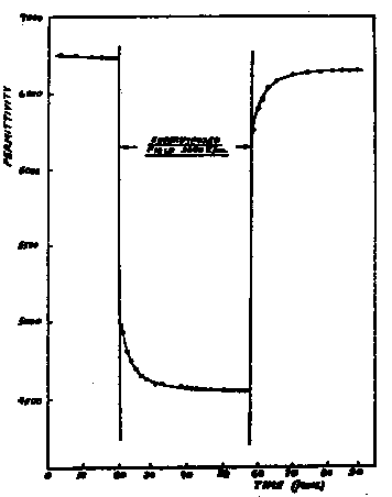
the higher initial values. All these features are shown in fig.5. The nearer
the temperature to the Curie point the bigger were the effects. Similary,
the higher the the field the clearer the effect. In fig.6a) and fig.6b)
these results from fig.5 are represented as slopes
which is the slope of characteristic D-E diagram of the capacitance. The
principal electrical test setup is shown in fig.4. Due to internal relaxation
of the crystal the material slowly shifted its permittivity values under
field influence of 3300V to lower permittivity values. After switching
off the field the permittivity values jumped again to higher which -however
were lower before the material was charged and relaxed againwith time to
the higher initial values. All these features are shown in fig.5. The nearer
the temperature to the Curie point the bigger were the effects. Similary,
the higher the the field the clearer the effect. In fig.6a) and fig.6b)
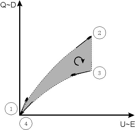
these results from fig.5 are represented as slopes ![]() in the D-E diagram of the dielectrics in order to make conclusions on the
qualitative behavior of the dielectric. Under zero voltage the positition
and direction of the D-E-lines can be concluded clearly from the data in
fig.5. For higher voltages two possibilities exist. The first is represented
in fig.6a) and reproduces the qualitative shape of the D-E-line of a paraelectric
material. However, it represents a negative overunity hysteresis area and
would confirm very well a prediction made in a prior article [2].
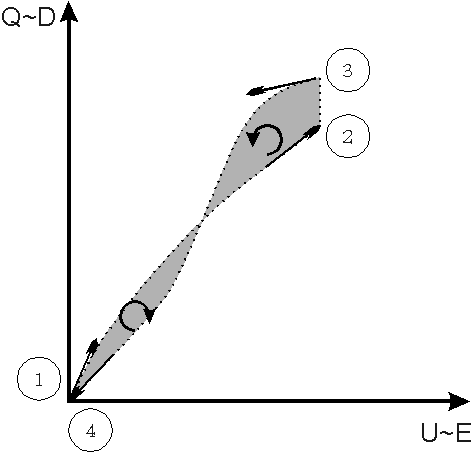
The other possibilities shown in fig.6b. Here the quite unsual paraelectric
D-E-discharge line of the capacitance can cross the D-E- charging line
one or more times. In this case no prediction can be made by the author
because under this conditions positive and negatively oriented working
areas appear in the closed working area of a cycle of the dielectrics and
allow no prediction at first hand.
in the D-E diagram of the dielectrics in order to make conclusions on the
qualitative behavior of the dielectric. Under zero voltage the positition
and direction of the D-E-lines can be concluded clearly from the data in
fig.5. For higher voltages two possibilities exist. The first is represented
in fig.6a) and reproduces the qualitative shape of the D-E-line of a paraelectric
material. However, it represents a negative overunity hysteresis area and
would confirm very well a prediction made in a prior article [2].
The other possibilities shown in fig.6b. Here the quite unsual paraelectric
D-E-discharge line of the capacitance can cross the D-E- charging line
one or more times. In this case no prediction can be made by the author
because under this conditions positive and negatively oriented working
areas appear in the closed working area of a cycle of the dielectrics and
allow no prediction at first hand.
Therefore, the standard thermodynamic description of the problem is
not possible because the effects are due to time-dependent varying material
parameters. Standard thermodynamic would need unique material properties
independent from time.
Therefore, whether it is possible to rebuild and improve such materials
is a task for a material scientist now and can not be followed here by
me here.
Bibliography:
1) G. Engeln-Müllges, F.Reutter
Formelsammlung zur numerischen Mathematik mit C-Programmen
B.I. Wissenschaftsverlag Mannheim,Wien,Zürich 1990
2) http://www.overunity-theory.de/bauer/index.html
3)J.R.Partington, G.V. Planer, I.I.Boswell
Philos.Mag., Ser.7, 40,(1949)157-175
4)H.J. Martin
Die Ferroelektrika
Akademische Verlagsgesellschaft Leipzig 1964
5) W.Koch, Z.Naturforschg. 13 a, p.303-310[1958]
Ferroelekrische Nachwirkungerscheinungen an polykristallinem Bariumtitanat