Abstract and Introduction
The experiment described here was done
by Alexander Bucher and is described in his "Jahresarbeit of the 12.class"
from a Waldorf highschool. He realized a simplified version of the known
Wuerth rotator. His measurements showed no influence on the rotor's
angular velocity due to the braking process of Wuerth's parametric rotator.
This observations are confirmed by Wuerths own experiments. They contradict
to the predictions made by the theory in the top document.
The experimental setup
It was built a typical simple Wuerth rotator
setup without belt translation, comp. fig1a) and b).
The radial disks were wheels of a wheel-barrow
whose tires were cutted open in order to fill them with pebbles as weight.
Then they were closed with tape again.
The whole setup was built into a big chest
(100cm x 90cm x 33 cm) made of wood comp. fig. 4. The cover and the bottom
of the chest consisted of plates of wood of 25 mm thickness. The distance
parts between the plates were 8 boards of 30cm length and of a cross section
of 5cm x 20 cm. They were connected by screws to the bottom plate. The
whole box was closed using 4 threaded rods of 12mm strength which made
the whole setup stable and easy to open. A bearing with an inner diameter
of 30 mm was fixed in the bottom plate. The central 30 mm diameter axis
was set in there.
The slab, comp. fig.2 consisted of two
80 cm long tubes of rectangular profile (5cm x 3cm). In the middle there
was the 30mm hole for the central axis, at the ends there were the 14mm
holes to fix the rotor axis. The axis of the rotors were hollow tubes of
20mm of 3mm strength (plunger stuff !). Using a (14mm diameter) threaded
rod in the tube the axes could be fixed by nuts to the slab. Two bearings
from a old bicycle were used between the lower slab arm and the rotor wheels
to allow a easy rotation without slipping.
In order to drive the rotor a drum was
connected to the central axis on which a rope was winded off if the slab
was accelerated by pulling the rope. The rope could be clicked out automatically
in the end of the process, comp. fig.3. The braking mechanism on it was
more difficult to develop. The final mechanism allowed either to fix the
rotor permanently either braked the rotor by the bolt after the wind off
process. Therefore, the drum was not totally fixed to the central axis
and could be turned 1/8 rotation on the central axis. If the rope was winded
off the drum turns back 1/8 rotation and shifts two bolts (tube profile
(20mm x 10mm) outwards which served to stop the rotor's rotation instantly
if they contacted one of the 4 threaded rods (diameter 8mm) fixed in holes
on the rim with nuts in equal distances. The rods projected 3cm outwards
and crashed on the bolts if they were moved out.
Measurements
The setup was set in rotation using a
rope and a weight, comp. fig.5. With free rotors 4.1 sec were necessary
for the weight to come down to the ground. The highest rpm of the rotor
were 38.8 . If the rotors were always blocked, 4.46 sec were necessary
and the maximum rpm was 35.2 , meaning that the free rotor system could
be accelerated to higher rpm in shorter time at the same force.
For exact measurements 10 runs with the
apparatus had been done. The angular velocity had been measured by a tacho
from a bicycle and is recalculated here in rpm. A weight of 6.22 kg was
used, each rotor weighted 12.435 kg. The pulling weight fall down a distance
of 3,38 m. The rope disconnected automatically from the rotor after winding
off. The measured values can be found in the table below (all data in rpm
units)
| Rotors always braked | Rotors braked after wind off | Rotors not braked |
| 35.5802 | 40,3596 | 40,3596 |
| 37,7044 | 39,8286 | 40,3596 |
| 37,7044 | 40,3596 | 39,8286 |
| 37,7044 | 40,8907 | 40,3596 |
| 37.1733 | 39,2975 | 39,8286 |
| 37,7044 | 39,8286 | 39,8286 |
| 37,7044 | 39,8286 | 40,3569 |
| 37.1733 | 40,3596 | 39,8286 |
| 37,7044 | 40,3596 | 40,3596 |
| 37,7044 | 40,3596 | 40,8907 |
| mean: 37,38576 | mean: 40,1472 | mean: 40,19995 |
In a second experiment the rotor was rotated by an external motor. The
rotor was accelerated to 40 rpm. Then, the motor was switched off and served
as a brake to decelerate the motion of the rotor and were not braked. The
time was measured necessary to come down from 40 rpm to 15 rpm.
If the rotor wheels were free running without brake the time necessary
to decelerate was 15,04 sec, with brake in the rigid state 17,63 sec. This
meant that more energy is obtained from the rigid state under same conditions.
If the rotor wheels were free running initially and then were braked,
again no significant loss of angular velocity could be measured similarly
like in the first experiment.
Discussion
If one compares the result with the known
theory, the results do not fit at all with the prediction, which can be
made by theoretical calculation. Acc. to the recent calculation the braked
system built is comparable with an inelastic recoil experiment applied
to angular moment. Therefore, acc. to the theory there should be a loss
of energy. The empirical observation contradicts to this predictions. Regarding
overunity efficiency the result seems to be better than any theoretical
prediction of any author.
Therefore, other possibilities should
be taken into account. We propose a modified experiment with only one rotor.
The chest itself should stand perpendicular with the rotation axes horizontal.
If the unbraked rotor is released at the top point it is accelerated falling
down in the gravitational field. If the rotor goes through the lowest point
the brake is switched on. If the observations are interpreted correctly
by the experimenter and if there exist not to much friction it should be
possible that the rotor overcomes the top point if it rises again in the
gravitational field. This would be a simple proof of overunity.
Regrettably the whole setup was destroyed
by a local water flood. Nevermind, the check of this simple question could
be done with not too much effort using a simple modified setup, comp. fig.6,
instead of a complete the reconstruction of the whole setup.
References
1) Alexander
Bucher, Freie Energie, Jahresarbeit 12.Klasse of 1998
http://www.agentsnoopy.online.de/projekt/energie.html
2) W.D.
Bauer The parametric rotator - the Wuerth power booster
http://www.overunity.com/rotator/rotator2.htm
Captions:
Fig. 1a: top view of the whole setup
1 threaded rod, 2 ground plate, 3 distant parts, 4 rotor axis,
5 slab, 6 central axis, 7 rotor wheels
Fig2: Side view of the cross section of the rotor
1 threaded rod, 2 nut, upper slab, 4 central axis, 5 rotor axis
tube, 6 nut, 7 lower slab, 8 drum for rope, 9 bearing, 10 bottom plate
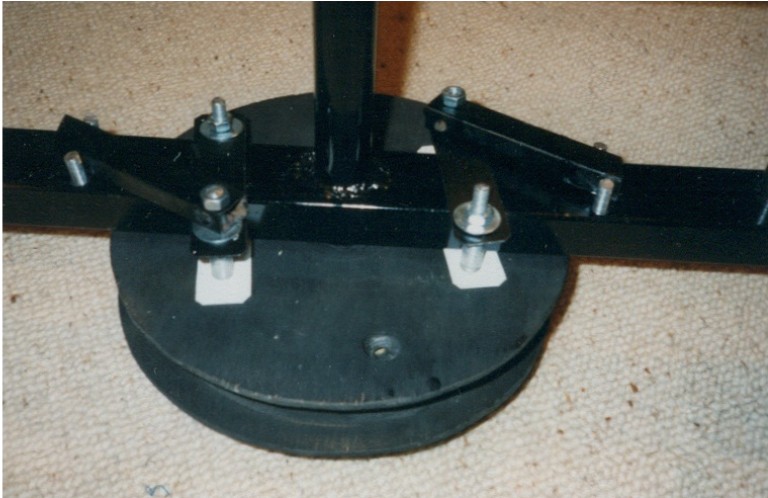
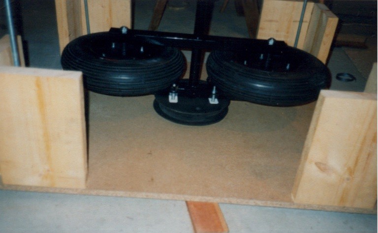
Fig 4: Foto of the whole setup
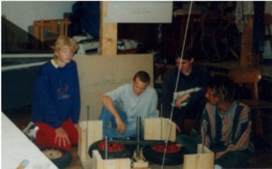
Fig 5: During the experiment
Fig.6: A modified setup of the above experiment acceleration and deceleration
by the gravitational field.
Is it relevant where the rotor bounces at the slab ?
a) If the rotor bounces on the stoppers at the slab inside it possibly
accelerates the slab only slightly because the torque of the momentum is
low due to the little radius there. The top point of the cycle should
be overcome. This would be a perpetuum mobile effect.
b) If the rotor bounces at the slab outside it should brake the slab
considerably due to the high radius there. The top point of the cycle should
not be reached.