by W.D.Bauer and Stefan Hartmann![]() released 11.8.97
released 11.8.97
by W.D.Bauer and Stefan Hartmann![]() released 11.8.97
released 11.8.97
Abstract:
A flux gate generator was constructed and tested out. The results of
the measurements are reported. They do not falsify the usual belief in
energy conservation. The results are compared with the literature and possible
improvements of the generator are discussed.
1) Introduction
In order to test out the correctness of previous predictions regarding
the behaviour of a Brown-Ecklin generator we undertook the task to build
up a modified flux generator and to test it out.
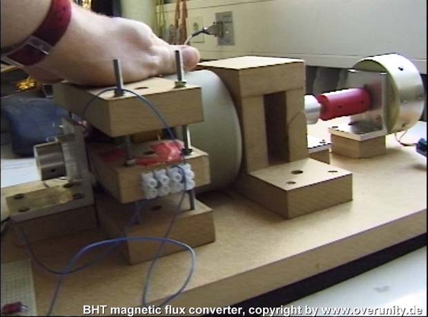
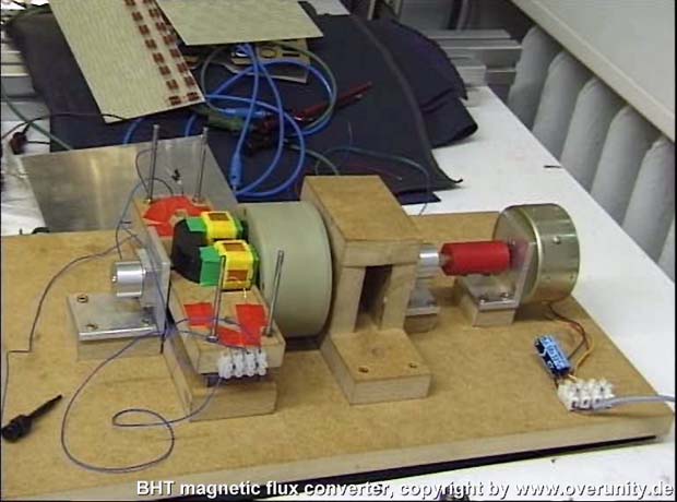
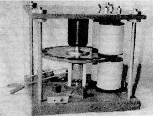
2) Setup
Acc. to a previous proposal [1]
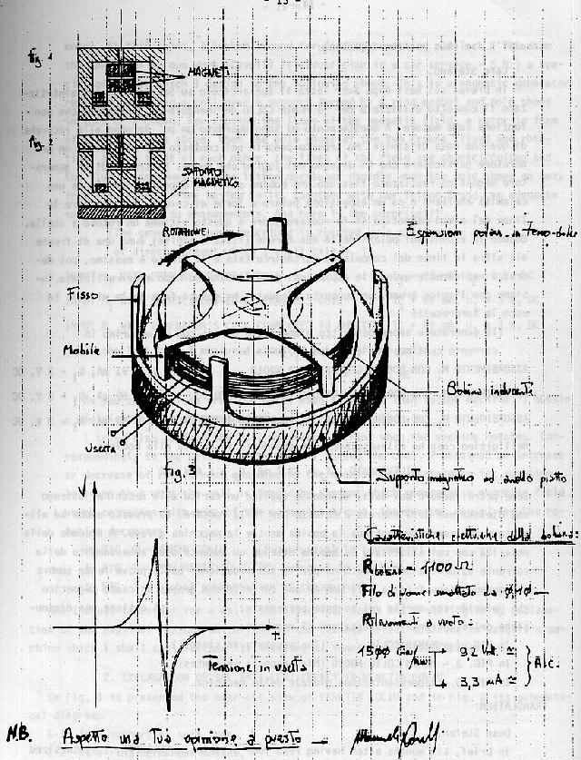
we built up a two circuit Brown-Ecklin generator. The revolver drum-like
rotor housing of the fluxgate cores was made of plastic and contained four
laminated iron cores. One stator side contained 4 holes for 2cm diameter
and 2cm length cylindical magnets. They could be filled with stronger neodymium
magnets of 1 cm length of 3 weaker neodymium magnets of 0.7cm length. The
magnetic circuits were closed at the backside of the magnets by a piece
of undefined steal from the stuff. Later we used two pieces 2cm x 2cm x
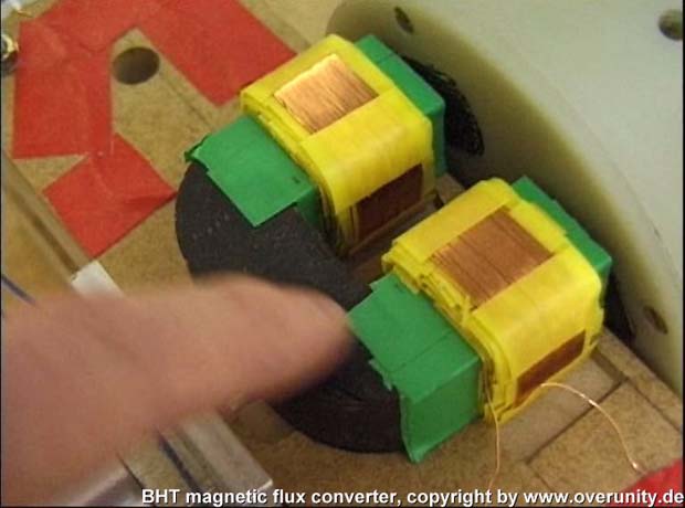
6cm PERENORM. The other side of the stator contained 2 U shaped laminated
transformer cores each with two coils wound on the horseshoe legs. Each
coil had about 500 turns (8 layers of wires, 2.2cm coil length each at
the first and lowest layer, 0.8mm diameter wire thickness, inner resistance
of each coil 7-8 Ohm), i.e. per U core 1000 and in sum (if switched in
serie) 2000 turns. The cross section of the horseshoe was 2 x 2 cm2 .The
distance between each U legs was 2cm as well. The material ( firm could
not be identified) had a saturation of probably about 1,5 T which is typical
for such parts used as transformer cores. The driving motor was a LEAR
JET capstan motor. Its efficiency was not specified. However, it is known
that such motors have typical efficiencies of 30%(long life version) to
50%(high efficiency versions).
As current source of the motor we used a very stable standard electronic
power supply in the voltage regulation mode. As load of the generator we
used usual electronic resistors switched in serie on a board.
For measurement of input motor voltage and current we used two standard
4.5 digit multimeter. The output voltage and frequency of the generator
was measured by HAMEG scopes (20Mhz bandwidth and higher). The frequency
was controled additionally by a multimeter containing a frequency counter.
Some pictures of the generator are shown in fig.2a - ???. The complete
interconnections of all instruments are shown in fig.3.
Tab.1: list of used materials
iron cores:
material:VACOMAX, firm:VACUUMSCHMELZE, ~200000, saturation 0.7 T, each
core 36 lamellas of 0.5mm thickness isolated by grafitti paint from a spray
dose, length 5cm of lammellas, diameter of the core~2cm;the iron was baked
out 5h under H2 at 1100 degree Celsius for 5 hours
magnets:
a) strong neodymiums: NE 201 from IBS[2]; energy product E x H
=250 kJ/m, remanence Br=1.2T, diameter, 2cm length 1cm
b) weaker neodymiums: NA 002 from IBS[2]; energy product E x H
=80 kJ/m, remanence Br=680mT, diameter 2cm, length 0.77cm
irons to close the flux:
material: PERENORM firm:VACUUMSCHMELZE, saturation 1.5T
motor:
LEAR JET capstan motor part nr. 357-9102-001 type CDM ID 131039
typical data: 24V DC; without load:108mA, 4640 rpm; with load: 450mA,
3400 rpm
3) Experiment and results
The experiment was designed in the following way: we used the generator
as a tool to measure the efficiency of the capstan motor. We measured the
efficiency of the motor acc. to the definition
netto efficiency = (power output) / (netto power input)
where netto power input = input with load - input without load. Input loads (DC current!) were calculated acc. to P=U.I where P= power, U=voltage and I=current. In order to include the inner resistance of the coil the output power of the generator was approximated acc. to
![]()
If a diode was in the circuit the circuit we used the formula
![]()
If we get efficiencies significantly higher than expected for these
motors then energy conservation in the usual sense would be falsified and
overunity of the generator is probable.
After the first playing around we saw that maximum output was achieved
if the airgap between the U shaped coil cores and the flux cores was bigger
(i.e. 5.6mm)and tight (i.e. 0.5mm) between the magnets and the rotor. All
coils were switched in serie. Furthermore, it was important that the left
magnets of the circuit had the same polarity and the right magnets the
opposite (contrary to fig. 1). We used strong and weaker neodymium magnets,
but the measurements were done with the weaker ones because this reduces
mechanical losses by vibrations. All measurements were done at constant
1875 rpm (i.e. 31.25Hz) which is equivalent to a AC current of 125Hz from
the generator seen at the scope screen shown in fig. 4
The complete copy of the protocol in chronologial order of the relevant
measurements can be found in the appendix. Fig.5a-c shows efficiency vs.
resistance calculated from our first measurements from 14.6.97 measured
with or without a diode in the circuit in each direction, comp.appendix.
After this measurements we saw that the value of the input power without
load shifted with time due to a slight wandering of the lammellas in the
core and other imperfections of construction. Therefore, we calculated
worst and best case efficiencies taking the better (higher) value and the
more worse (lower) value of input power without load- measured before or
after the measurements under load. The deviations of these values were
the most biggest factor responsible for the error bars of measurement,
therefore we neglected the other factors.
We saw that the efficiency was slightly (significant?) enhanced with
diodes but the direction of the diode polarisation seemed to be insignificant.
Some efficiency values were higher than 50%.
Because we got best values of higher than usual capstan motor efficiencies
we had a closer look to this values and measured alternatively under load
and without load at the most promising resistance values, comp. data in
appendix from 6.7.97. Now, the efficiencies were about 40% .
Another interesting feature could be seen at decreasing low load resistances,
comp. data in appendix from 12.7.97: Although the load decreases and the
current rises the power to drive the motor decreases indicating lower back
torque of the stator coils at higher current. However, it is clear from
these measurements that the power delivered from the coils under this conditions
decreases as well.
4) Discussion
Acc. to our generator measurements we found no region of significant
overunity efficiency which would falsify the usual belief in energy conservation.
However, the AC wave form shows an assymmetry which has been calculated
qualitatively previously. Surely the wave form could be made more similar
to the form calculated if the distance between the rotor cores (or the
diameter of rotation) would be bigger during one revolution. Therefore,
we believe that our model ansatz is correct principally although it needs
modification to be numerically correct.
However, the output energy values calculated by the theory deviate
a order of magnitude from the reality measured here. It is clear that the
model presented has the weak point that the model network of magnetic resistances
has been assumed with only less backing by a three dimensional field calculation.
Furthermore, the non-linear behaviour of the cores is neglegted. Therefore,
we see the following possibilities to increase the efficiency of the generator:
1) Possibly the back torque of the horsehoe coils is too high because
the saturation of the cores is too high compared with the flux which can
go through the rotor cores. If we can calculate typical currents of 40mA
and higher in the coils the H-field of the coils is ~10A/cm which means
that the iron (typ. saturation values 1A/cm) of the U cores would be in
saturation at 1.5T where the coils are.
2) By reducing the length of the rotating iron cores the magnetic dipol
moment of the core can be reduced as well. As a consequence the torque
exerted on the flux gate cores should decrease as well.
If we compare our results with the known facts and summarize than we
have to say that our measurements do not falsify the conservative belief
in energy conservation which is contrary to other observations which claim
to have measured "negative" incremental efficiencies which is quite contrary
to usual energy conservation because these generators accelerate if power
is drawn from it. (However, until now, no generator is known which have
absolute efficiency = output/input grater than 1.) Some of such observations
were made by Marinov [3](recently deceased). Acc.to his considerations
and observations it is important to have big coils (i.e. big inductivities
in the circuit) to shift the phase of the current in the coil that Lenz's
law inverses in effect and the generator becomes self-accelerating. Futhermore,
the effect exists only at higher rpm. Some of Marinov constructions can
be found in fig.6a-???. Greg Watson [4]
means that it is important to have a magnetic design which makes sure that
the flux gates are attracted by the coil under current during the closing
phase of the magnetic cycle.
Similar observations of negative incremental efficiency has been made
by Pete J. Aldo [5] who used another so called SAG-flux gate design proposed
by Brown [6].
Therefore, we believe that the problem of the energy balance in electromechanic
enngieering is still open for further research.
Acknowledgement: We thank Mr. Thiede for doing the biggest part of the mechanic work.
Bibliography:
[1] W.D. Bauer
The Brown-Ecklin Overunity Generator - A Theoretical Analysis
[2]Magnetismus - Dauermagnete Werkstoffe und System
Catalog by IBS Magnet Ing.K.H.Schroeter Kurfuerstenstr.92 D-12105 Berlin
[3] S. Marinov
all references below are self publications of S. Marinov at "East-West
Publishers" Graz Austria
1)The thorny way of truth IV 1991 p.8
The perpetuum mobile "Il nicolino di Veneto" VENETIN COLIU
2)Deutsche Physik Vol.1 No.1 1992 p.40
The self accelerating generator VENETIN COLIU
3)Deutsche Physik Vol.2 No.5 1993 p.5
When will the self accelerating generator VENETIN COLIU become a perpetuum
mobile ?
4) Deutsche Physik Vol.2 No.7 1993 p.15
The self accelerating generator VENETIN COLIU VI
5) Deutsche Physik Vol.3 No.10 1994 p.8
The self accelerating generator VENETIN COLIU VII
6) Deutsche Physik Vol.3 No.10 1994 p.37
The generator VENETIN COLIU VI coupled with a Robert Adams motor
7) Deutsche Physik Vol.3 No.11 p.35
Discovery of an important additional cause for the anti-Lenz effect
in the generator VENETIN COLIU.
[4] Greg Watson's
homepage
description of the
DNMEC generator
[5] Pete J. Aldo, pers. communication
[6]Brown, Paul The magnetic distributor generator 1982
copy of a report, 1982
entry: Dr. Nieper Gravity Folder
was available from "list of shielding theory of gravity papers" at
Admiral Ruge Archives of biophysics and future science
Keith Brewer Library, Richland Center, Wisc. 53581 USA
Appendix: Copy of the protocol of our measurements
data from 14.6.97 below: 125 Hz AC, electric circuit acc. to fig.3 .
1.run: without diode
| R /Ohm | Umot / V | Imot / mA | Upeak / V |
| INF | 14.557 | 281 | 16 |
| 396 | 15 | 317 | 14.5 |
| 374 | 15 | 317 | 14.5 |
| 352 | 15.001 | 319 | 14 |
| 330 | 15.001 | 316 | 13.7 |
| 308 | 14.9388 | 316 | 13.7 |
| 286 | 14.9388 | 318 | 13.5 |
| 264 | 15.0363 | 323 | 13 |
| 242 | 15.0728 | 325 | 13 |
| 220 | 15.0731 | 324 | 12.7 |
| 198 | 15.1044 | 328 | 12.3 |
| 176 | 15.1457 | 335 | 12 |
| 154 | 15.146 | 336 | 11.3 |
| 132 | 15.279 | 338 | 10.5 |
| 110 | 15.328 | 344 | 9.7 |
| 88 | 15.382 | 344 | 8.7 |
| 66 | 15.341 | 347 | 7.5 |
| 44 | 15.305 | 346 | 5.5 |
2.run below : with diode in circuit (direction not identified), other things dito
| R /Ohm | Umot / V | Imot / mA | Upeak / V |
| INF | 14.34 | 270 | 15.3 |
| 396 | 14.55 | 287 | 13.3 |
| 374 | 14.55 | 287 | 13.1 |
| 352 | 14.513 | 287 | 13 |
| 330 | 14.513 | 288 | 12.9 |
| 308 | 14.524 | 291 | 12.8 |
| 286 | 14.524 | 290 | 12.6 |
| 264 | 14.521 | 292 | 12.5 |
| 242 | 14.521 | 292 | 12.3 |
| 220 | 14.569 | 294 | 12 |
| 198 | 14.621 | 297 | 11.8 |
| 176 | 14.622 | 302 | 11.3 |
| 154 | 14.703 | 301 | 10.8 |
| 132 | 14.704 | 301 | 10 |
| 110 | 14.745 | 307 | 9.5 |
| 88 | 14.746 | 305 | 8.8 |
| 66 | 14.85 | 311 | 7.3 |
| 44 | 14.9 | 320 | 5.7 |
3. run below: with diode in circuit (direction opposed to last run), other things dito
| R /Ohm | Umot / V | Imot / mA | Upeak / V |
| INF | 14.331 | 276 | 13.5 |
| 396 | 14.54 | 290 | 13.5 |
| 374 | 14.54 | 291 | 13.5 |
| 352 | 14.54 | 288 | 13.2 |
| 330 | 14.54 | 290 | 13 |
| 308 | 14.57 | 289 | 13 |
| 286 | 14.62 | 293 | 12.6 |
| 264 | 14.62 | 296 | 12.4 |
| 242 | 14.62 | 293 | 12.3 |
| 220 | 14.62 | 297 | 12.1 |
| 198 | 14.71 | 302 | 11.8 |
| 176 | 14.71 | 303 | 11.4 |
| 154 | 14.71 | 302 | 11 |
| 132 | 14.71 | 307 | 10.2 |
| 110 | 14.82 | 311 | 9.5 |
| 88 | 14.82 | 311 | 8.6 |
| 66 | 14.93 | 319 | 7.4 |
| 44 | 15.01 | 325 | 5.8 |
| INF | 14.15 | 272 | 15.2 |
Run from 6.7.97 below: now with PERENORM at the back side of the magnets,
other things dito
notations: 0 =no diode, + =diode one direction, - =diode opposite direction;
| R /Ohm | Umot / V | Imot / mA | Upeak / V | efficiency/% | diode |
| INF | 14.755 | 289 | 17.5 | -- | 0 |
| 352 | 15.041 | 312 | 14.5 | 39-30 | + |
| INF | 14.633 | 287 | 17.5 | -- | 0 |
| INF | 14.66 | 282 | 17.5 | -- | 0 |
| 352 | 15.008 | 310 | 14.5 | 33-40 | - |
| INF | 14.642 | 288 | 17.5 | -- | 0 |
| 352 | 14.953 | 310 | 14.5 | 41-40 | + |
| INF | 14.609 | 288 | 17.5 | -- | 0 |
| 352 | 14.904 | 310 | 14.5 | 41-40 | - |
| INF | 14.629 | 287 | 17.5 | -- | 0 |
| INF | 14.5 | 285 | 17.5 | -- | 0 |
| 330 | 14.87 | 310 | 14.5 | 38-34 | + |
| INF | 14.5 | 284 | 17.5 | -- | 0 |
| 330 | 14.835 | 309 | 14.5 | 36-35 | - |
| INF | 14.445 | 284 | 17.5 | -- | 0 |
| 330 | 14.832 | 309 | 14.5 | 35-34 | + |
| INF | 14.423 | 283 | 17.5 | -- | 0 |
| 330 | 14.817 | 287 | 14.5 | 35-39 | - |
| INF | 14.469 | 287 | 17.5 | -- | 0 |
| 396 | 14.788 | 308 | 15 | 42 | + |
| INF | 14.459 | 287 | 17.5 | -- | 0 |
| 396 | 14.781 | 307 | 15 | 44-39 | - |
| INF | 14.43 | 285 | 17.5 | -- | 0 |
| 396 | 14.76 | 307 | 15 | 40 | + |
| INF | 14.42 | 285 | 17.5 | -- | 0 |
| 396 | 14.765 | 307 | 15 | 40 | - |
data from 12.7.97 (no diode) measurement at low resistances
| R /Ohm | Umot / V | Imot / mA | Upeak / V | AC/ Hz |
| INF | 14.77 | 347 | 16.5 | 125 |
| 22 | 15.86 | 423 | 3.3 | 125 |
| INF | 14.68 | 337 | 16.5 | 125 |
| 11 | 15.71 | 420 | 1.75 | 125 |
| INF | 14.77 | 329 | 16.5 | 125 |
| INF | 14.73 | 318 | 16.5 | 125 |
| 44 | 15.916 | 403 | 5.8 | 125 |
| 22 | 15.889 | 408 | 3 | 125 |
| 11 | 15.889 | 400 | 1.6 | 126 |
| 22 | 15.889 | 401 | 3 | 125 |
| 11 | 15.889 | 398 | 1.6 | 126 |